

How to Maximize Substation Reliability at a Lower Cost Using a Breaker-And-Half Scheme
/
High voltage transmission and distribution substations are where incoming and outgoing power circuits meet to form an electrical grid. When properly designed, any fault on an electrical system can be localized to the fault location without the need for a total system shutdown. Selecting the proper bus scheme within a high voltage substation will allow circuit reliability to be maintained cost-efficiently.
Single Bus Configuration
In a single bus configuration, each electrical circuit is connected via a single breaker to a common bus. In this arrangement, a total of 4 breakers are required for 4 circuits. While this is the cheapest configuration to construct and the simplest to operate based on the minimum number of breakers, system reliability is problematic. In the event of an electrical fault on the common bus, all associated circuits will be rendered out of service with a total systemwide electrical shutdown.

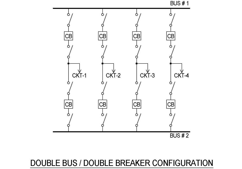
Double-Bus, Double-Breaker Configuration
With a double-bus, double-breaker configuration, two redundant electrical buses exist, each with connectivity to the electrical circuits via separate breakers. In this type of arrangement, a total of 8 breakers are required for 4 circuits. During a bus fault, only the faulted bus is shut down and circuit reliability is not compromised since the power flow can seamlessly re-route itself via the non-faulted bus. This arrangement is very reliable and allows great flexibility. However, due to the need for twice as many breakers, the construction cost is significantly greater.
Ring Bus Configuration
In this configuration, sectionalized buses are used for each electrical circuit with a tie breaker placed between each sectionalized bus. In this type of arrangement, a total of 4 breakers are required for 4 circuits. During a bus fault (or individual circuit fault), only the faulted bus is shut down and circuit reliability is not compromised since the power distribution can be seamlessly re-routed via the other side of the ring. While this arrangement is reliable and allows flexibility, the reliability factor decreases as the total number of connected electrical circuits increase. This is because no dedicated breakers are used for any circuit, so a circuit fault essentially causes the same impact as a bus fault.

Breaker-And-Half Configuration — Reliability while Saving Money
In this configuration, two redundant electrical buses are also used, but for every 2 circuits, 3 breakers are available with each circuit sharing a common center breaker. In this type of arrangement, a total of 6 breakers are required for 4 circuits. During a bus fault, only the faulted bus is shut down and circuit reliability is not compromised since the power distribution is seamlessly re-routed via the non-faulted bus across the breaker-and-half scheme. When designed properly with appropriate system protection, this arrangement is very reliable and allows great flexibility. Since this configuration uses fewer breakers than the double-bus, double-breaker configuration, the cost of construction is reduced.

Proper substation design should emphasize reliability to prevent a total systemwide electrical shutdown during a fault condition. For proper application of such schemes, it is always advisable to seek the advice of a licensed professional engineer and a licensed master electrician. Helios Electric can help you with both.
